CAD / Project story
Combined Shape and Offset Prototype
Move simple shapes and inspect the boundary they make.
Rectangles as building blocks
Combined Shape and Offset Prototype is a grid-based drawing tool for placing and moving rectangles. A selection tool and rectangle tool provide the basic interaction. Draw a shape, select it, then move it with the pointer or directional controls. The inspector exposes position, width, and height as numeric values.
The grid is part of the behavior, not only the background. Inspector values are rounded to twelve-inch increments, and dimensions have a minimum size. Direct manipulation and numeric entry therefore work within the same coarse unit system. The result is a small, controlled setting for exploring how simple pieces meet.
Where shapes meet
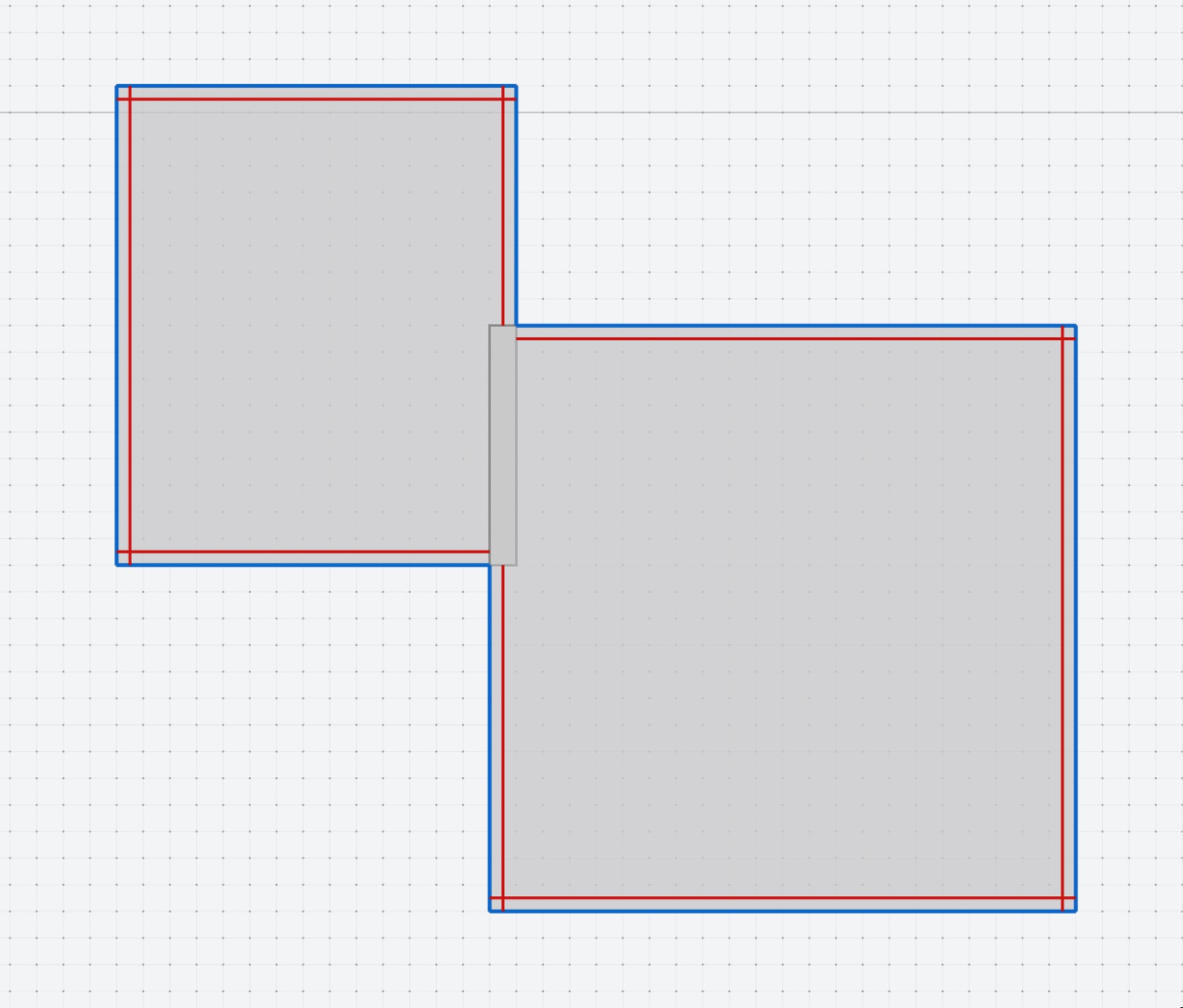
The interface states two placement rules: rectangles may overlap by up to twelve inches, and complete overlaps are not allowed. The combined perimeter is drawn in blue. In the existing project image, two offset rectangles form a stepped outline, with red inset lines showing another reading of the edges.
Those lines distinguish the individual pieces from the boundary of their arrangement. Moving one rectangle can change the outside outline while leaving the other piece in place. The prototype makes the overlap itself visible, so the relationship can be inspected at the join instead of inferred from a distant view.
A focused geometry study
Pan, zoom, and reset-view controls support looking closely at the result. The selected shape can be deleted or adjusted through the inspector, and the control help explains the drawing gestures and placement rules. The limited set of tools keeps the geometry easy to change repeatedly.
This page describes the active two-dimensional editing interface. The repository contains broader application scaffolding, but the useful public study is the connection between constrained rectangle placement and the perimeter it produces. Open the prototype to draw a pair of shapes, bring their edges together, and compare the outline as you move one against the other.