CAD / Project story
Unit Configuration Prototype
Arrange repeated units without losing the individual positions.
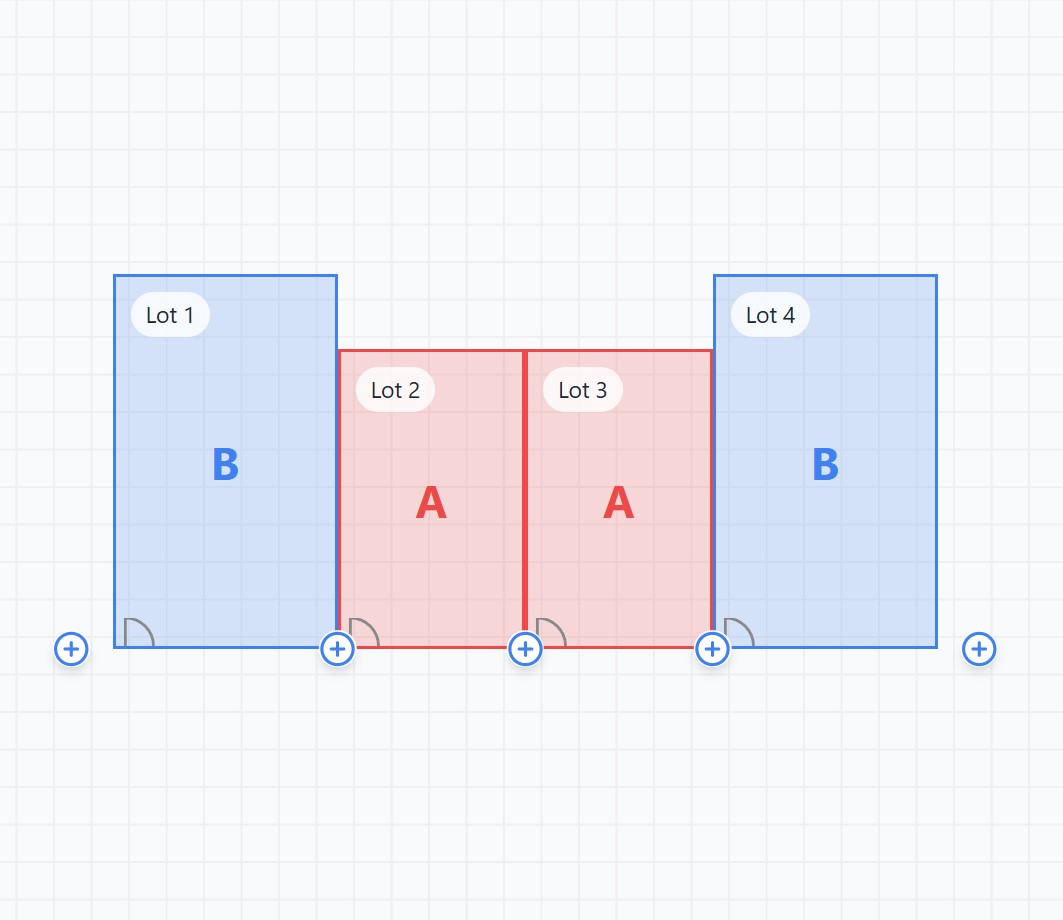
A sequence of units
Unit Configuration Prototype organizes an arrangement as numbered positions with assigned unit types. The left panel sets the number of units, from one to ten, and provides an assignment for each position. The drawing shows those choices as adjacent, colored footprints on a grid.
The separation between a unit definition and its position is visible in the interface. A type can appear more than once in the sequence, while each lot still has a distinct position to select. The example pictured here uses a B, A, A, B arrangement: two types form a four-unit composition.
Adjusting an instance
Selecting a position exposes its controls in the right inspector. The prototype includes a vertical offset for that selected lot, allowing a unit to move relative to its neighbors rather than forcing every footprint to share the same alignment. The arrangement remains readable as a sequence while its outline changes.
Unit creation and management provide the other side of the interaction. Definitions can be edited separately from the list of assignments. The canvas connects those abstract choices to a spatial result: changing a type or its position changes what the row looks like, not just a value in a table.
Keeping arrangements to compare
Named configuration presets provide a way to return to an arrangement after trying another. Save and Load sit with the configuration controls, alongside the list of presets. Import and export support carrying a configuration as a file. These are prototype data operations rather than a promise of a shared production library.
The study focuses on a compact relationship: types, positions, and the combined outline. Open the prototype to change the unit count, assign repeated types, and inspect the effect of an offset. The grid drawing makes those changes visible without requiring a detailed building model or a complete site layout.